Concrete Block Molds
Hollow Block Mold
Solid Block Mold
Solid Brick Mold
Interlocking Block Mold
Thermal Block Mold
Author:HAWEN Block Mould Manufacturer TIME:2026-11-11
A profile can fit its companion block yet raise a different question about leaving the mold. Assembly clearance concerns the surfaces of the finished units that meet. Release geometry concerns the relative path between a formed shape and its forming surfaces. Increasing a mating gap does not automatically remove an obstruction along that path.
Keeping the two questions separate helps a buyer respond to a manufacturing review without casually changing the required connection. The useful result is a precise account of which geometric concern a proposed change addresses—and which remains unresolved.
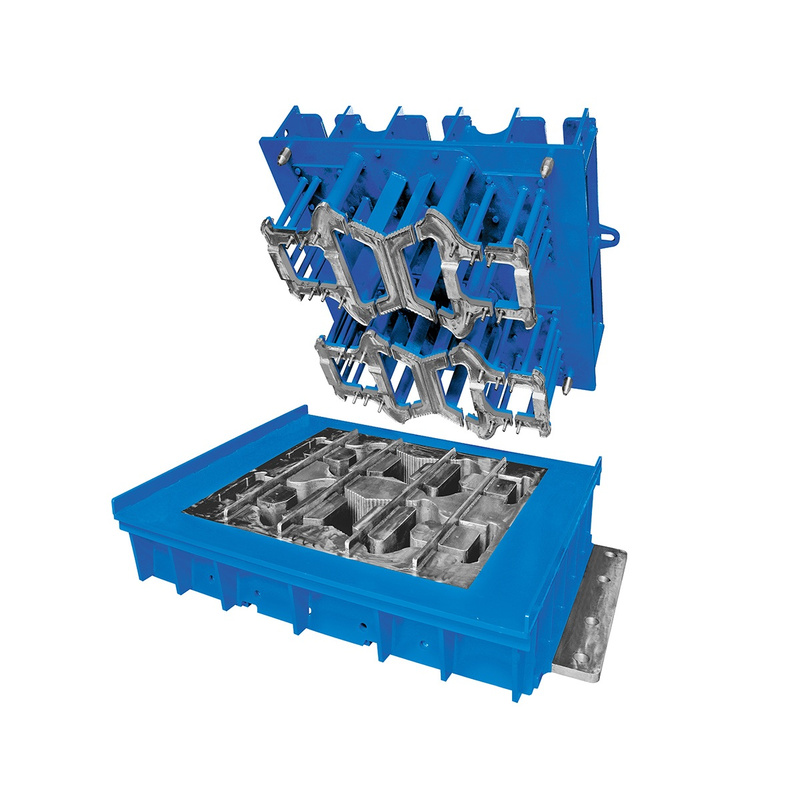
HAWEN's interlocking masonry tooling scope asks for both mating surfaces and their intended clearances. The assembled relationship might include a projection and its companion recess or other specified locating features. The approved design determines the intended dimensions and fit.
In an abstract example, a projection sits within a companion recess with a declared gap between selected surfaces. Enlarging the recess could change that gap. It would also change the final-unit relationship, so the responsible product designer must assess the effect rather than treating it as an inconsequential manufacturing adjustment.
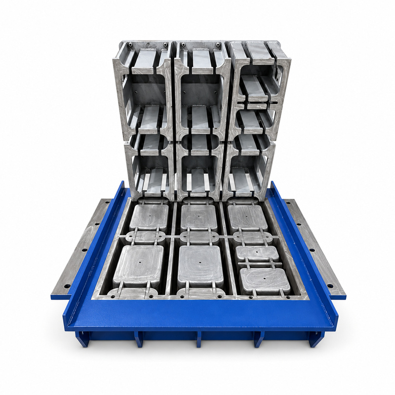
This is the assembly question: how do the defined finished surfaces relate in their intended arrangement? It does not yet describe how the tool separates from the forming product.
For a separate geometric thought experiment, assume rigid shapes and a single straight relative withdrawal upwards. Imagine a wider shoulder below a narrower exit. If that shoulder has to pass through the exit without rotation, deformation or another movement, the stated straight path is obstructed.
The point is directional. A drawing that identifies an obstruction for one translation does not establish what happens under a different arrangement. All features along the declared path matter; one convenient section is not a complete release assessment of a three-dimensional tool.
A tapered surface illustrates another distinction. Its separation from a corresponding surface can increase as relative motion proceeds in one direction. That geometric separation is different from a deliberately specified gap between two finished blocks. Even where both features appear in one section, they serve different relationships.
These descriptions do not declare that an actual concrete product will release successfully. Friction, product condition, forming behaviour and the actual machine/tool arrangement remain outside the rigid-path demonstration. Nor do they prescribe a taper angle, a surface treatment or a moving-tool mechanism.
Suppose a review note says “increase clearance” without naming the surfaces. That phrase is incomplete. It might mean changing the final mating relationship, changing space between tooling components or revisiting the product/tool path. Those are different technical proposals.
Return to the abstract shoulder. Increasing a gap between finished companion blocks could leave the shoulder and its narrow release exit unchanged. The assembly relationship has changed while the directional obstruction remains. The proposed response has therefore not answered the stated release question.
One way to make the reasoning visible is to name the three objects: finished block A, companion block B and forming surface T. The assembly gap belongs to A meeting B. The hypothetical shoulder obstruction belongs to A moving relative to T. If a proposal changes only B, while A, T and the declared translation remain identical, that change cannot remove the intersection between A and T. This is a statement about the defined geometry, not a conclusion about which tooling solution should be built.
The reverse can happen as well: a proposed geometry change aimed at the release path could alter a locating surface needed by the finished unit. A manufacturing concern does not make the original connection function disappear. Both requirements need a coordinated technical decision.
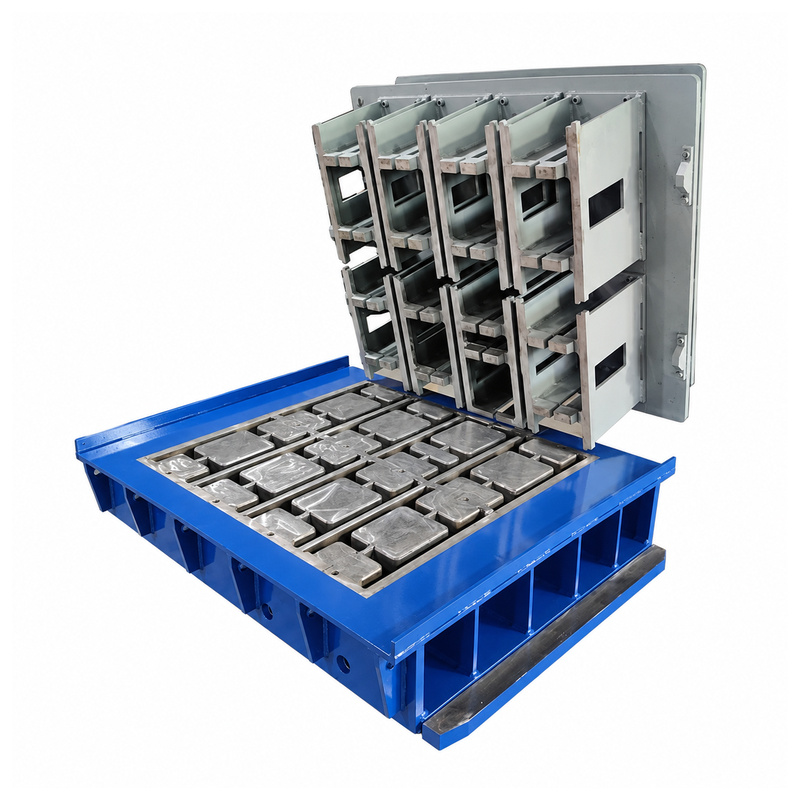
A useful reply identifies the proposed changed feature and the relationship it is intended to resolve. It then states whether the companion-unit requirement remains the same or needs its own review. This is more informative than approving the word “clearance” while the drawing's actual function is still ambiguous.
CAD undercut analysis can visualise extraction concerns relative to a selected reference direction or split plane. Autodesk's documentation describes that geometric function. Software displays depend on their selected analysis settings; a colour is not a concrete-process acceptance criterion.
Ask which direction and geometry the analysis represents. If either changes, an earlier directional result cannot simply be carried over. At the same time, a result showing no obstruction under a simplified geometric screen is narrower than proof that a specific fresh concrete unit can be produced and released in routine operation.
For a new interlocking-block proposal, preserve the intended mating function while the manufacturer reviews the actual release arrangement. The decision to make is explicit: has the proposed change addressed the assembly gap, the directional geometry, or both? Any remaining concern can then be reviewed in its own terms instead of being hidden inside one unqualified clearance instruction.
Geometric terminology: Autodesk undercut-shading documentation. This reference explains analysis terminology, not HAWEN process settings or the release capability of a concrete mold.
 Tel: +8618359454595
 Email: sale@hwmachines.com
 MP/WhatsApp: +8618359454595
 Manufacturer Address:Nanan, Quanzhou City, Fujian Province, China