
 Cavities/Cycle
 Kerb Profile
 Certification
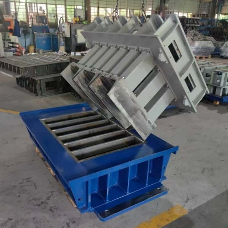
Custom Cross-Sections for Local Curb Designs
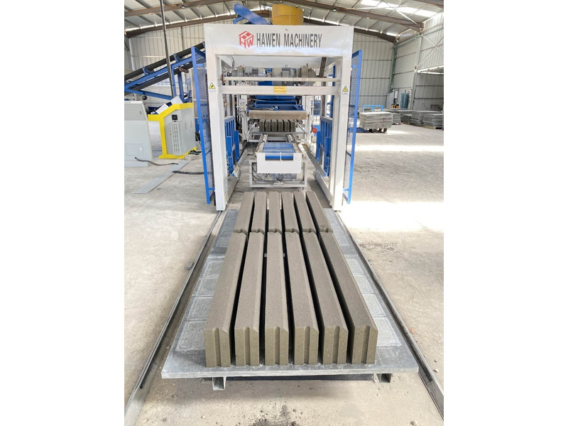
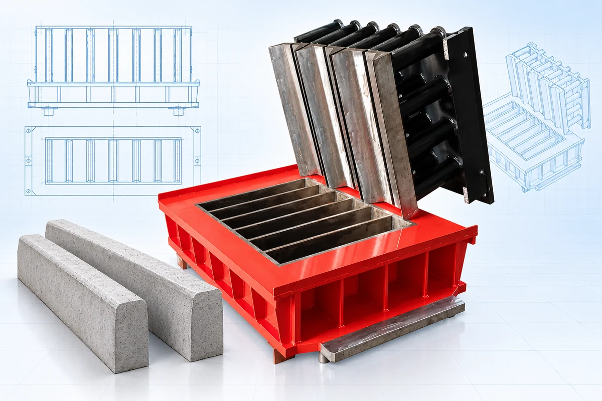
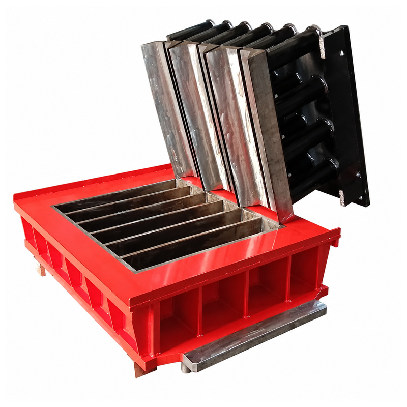
Molds can be developed for different curbstone lengths, widths, heights, and cross-sectional profiles. Detailed drawings allow the tooling to match your intended product geometry.
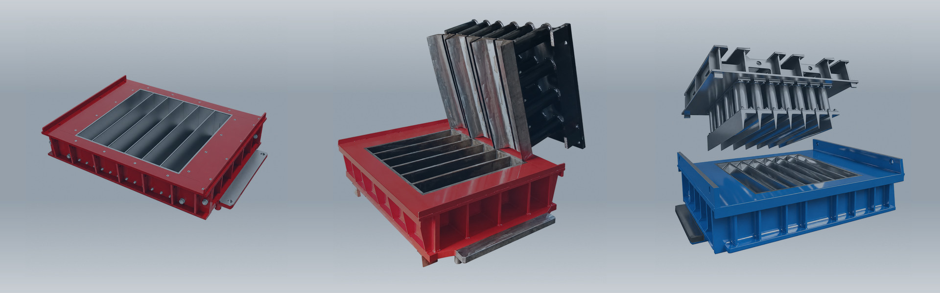
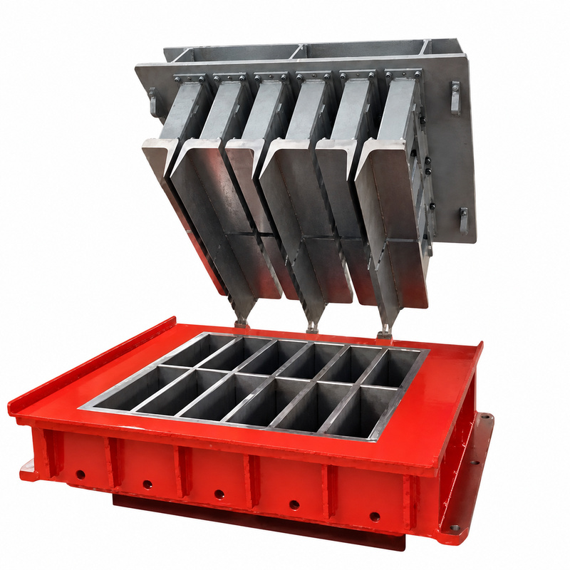
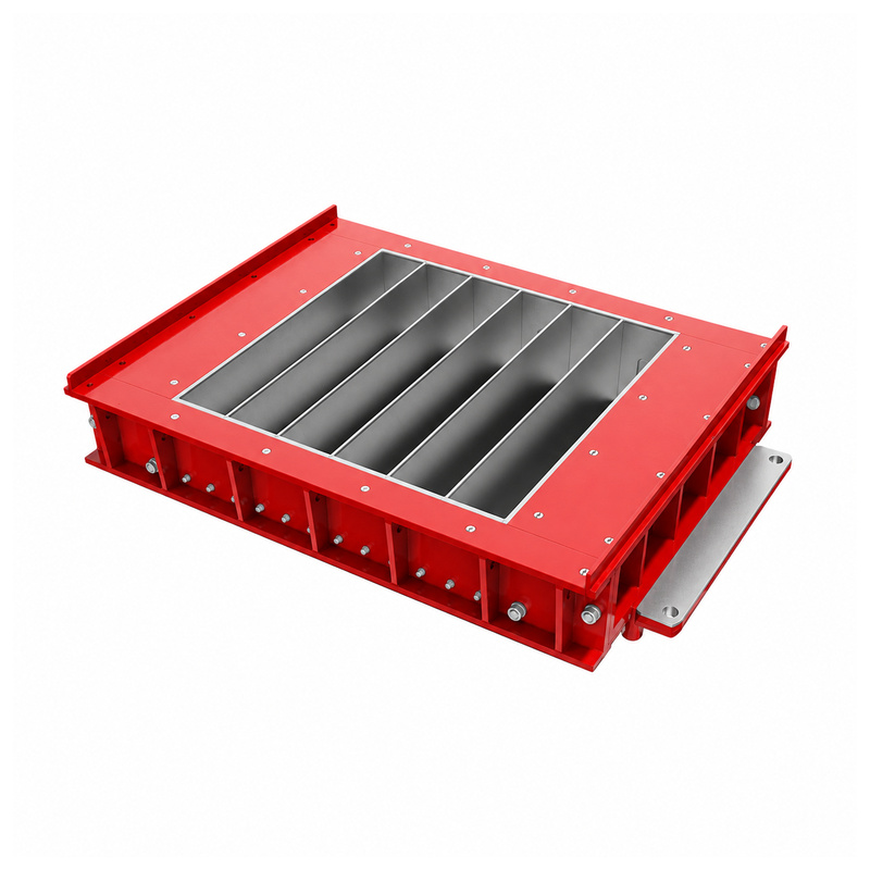
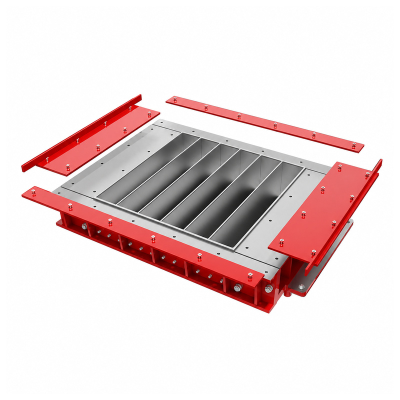
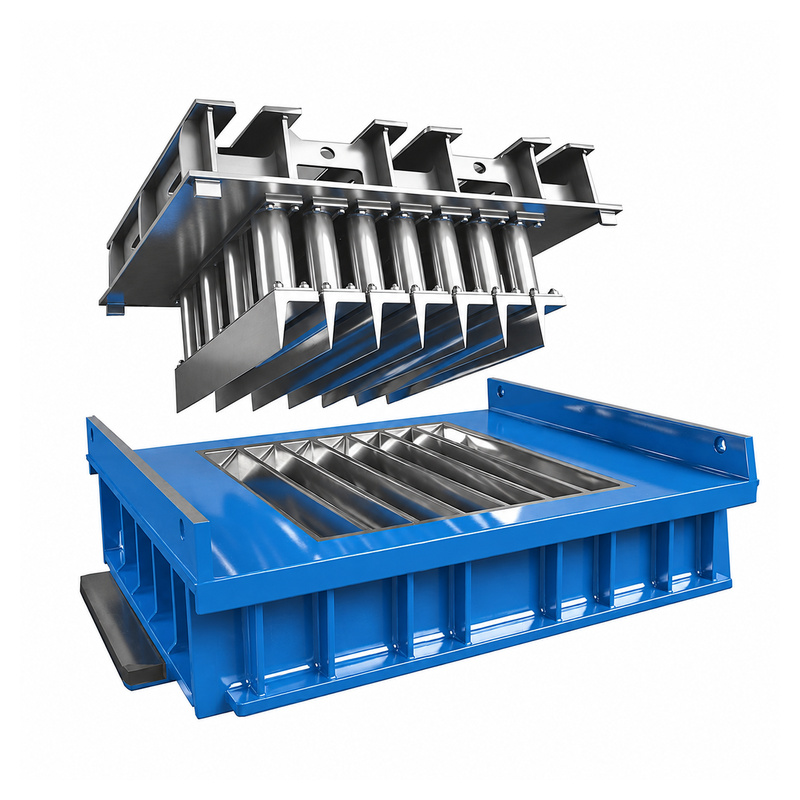
| Cavities/Cycle | Matching tamper and mould-box arrangement; cavity count requires the approved unit schedule. |
| Kerb Profile | Specified kerb cross-section and longitudinal profile; straight and special units reviewed separately. |
| Certification | CE, ISO |
| Cavities/Cycle | Matching tamper and mould-box arrangement; cavity count requires the approved unit schedule. |
| Kerb Profile | Specified kerb cross-section and longitudinal profile; straight and special units reviewed separately. |
| Certification | CE, ISO |
| Cavities/Cycle | Matching tamper and mould-box arrangement; cavity count requires the approved unit schedule. |
| Kerb Profile | Specified kerb cross-section and longitudinal profile; straight and special units reviewed separately. |
| Certification | CE, ISO |
| Cavities/Cycle | Matching tamper and mould-box arrangement; cavity count requires the approved unit schedule. |
| Kerb Profile | Specified kerb cross-section and longitudinal profile; straight and special units reviewed separately. |
| Certification | CE, ISO |
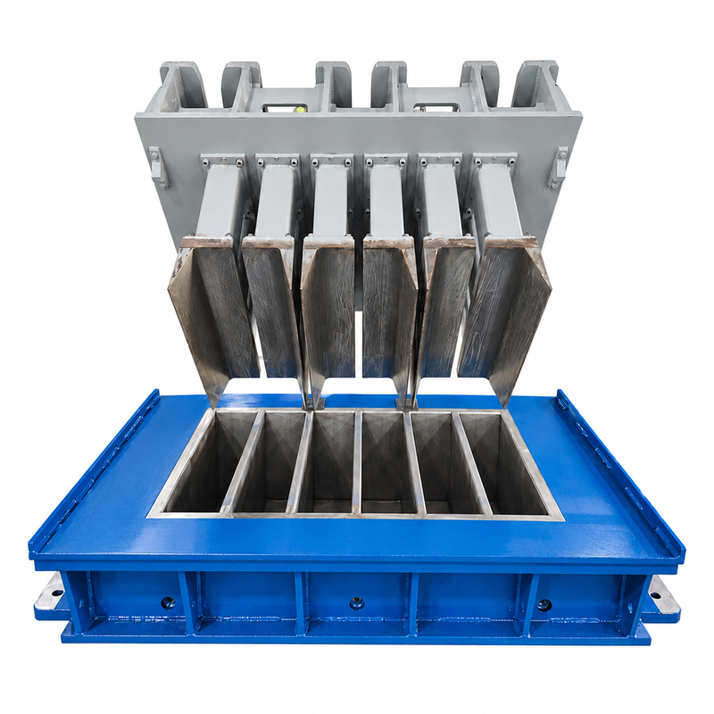
Molds can be developed for different curbstone lengths, widths, heights, and cross-sectional profiles. Detailed drawings allow the tooling to match your intended product geometry.
Curb faces, slopes, rounded sections, and edge details are incorporated where technically suitable. Precision reproduction supports consistent profiles across finished units.
Product dimensions and cavity arrangements are reviewed against the machine working area and production requirements. This helps establish a suitable configuration for manufacturing curbstones on your equipment.
Illustrative material concept
Check block mould material traceability by linking agreed certificates, steel batch identification, component records and inspection evidence.
Read material guideIllustrative material concept
Plan block mould wear components by checking forming geometry, replaceable parts, attachment details and inspection criteria against the approved design.
Read material guidePrepare your product and machine information. Let’s review the tooling.
Send the finished block drawing and dimensions, machine brand and model, pallet dimensions and the mould mounting details. For a replacement, include photos or drawings of the existing mould.
The review connects the block design with the receiving machine, pallet, mounting arrangement and available forming space. Share the relevant machine and mould drawings so the interfaces can be checked before a proposal is confirmed.
Select your project purpose and describe the current tooling or the block shape you want to produce. Existing mould photos and a dimensioned product drawing help the team identify the information still needed.
Confirm the approved block drawing, cavity arrangement, machine interfaces and agreed mould specification. Include any project changes in the enquiry so the proposal can be reviewed against the latest requirements.

 Tel: +8618359454595
 Email: sale@hwmachines.com
 MP/WhatsApp: +8618359454595
 Manufacturer Address:Nanan, Quanzhou City, Fujian Province, China