
 Mould Model
 Block Size
 Material / HRC
 Cavities/Cycle
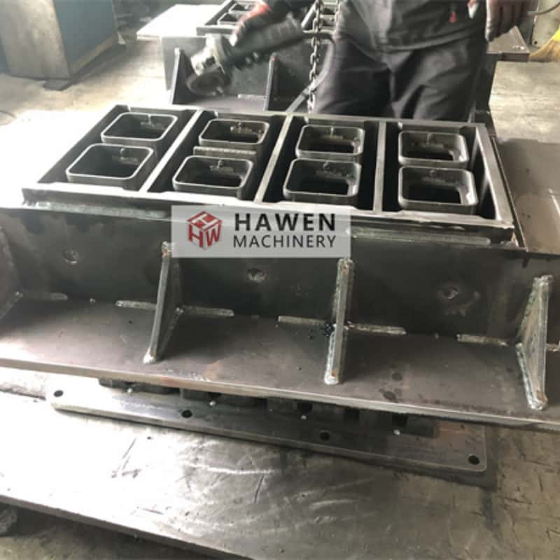
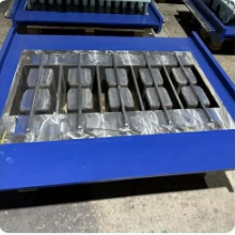
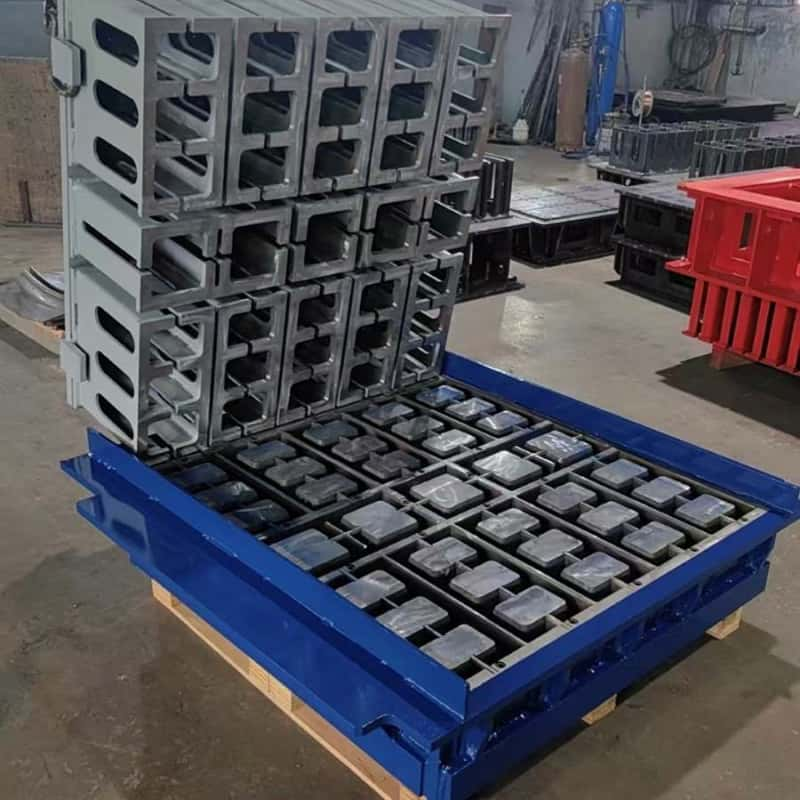
Multiple Cavities for Repeated Brick Production
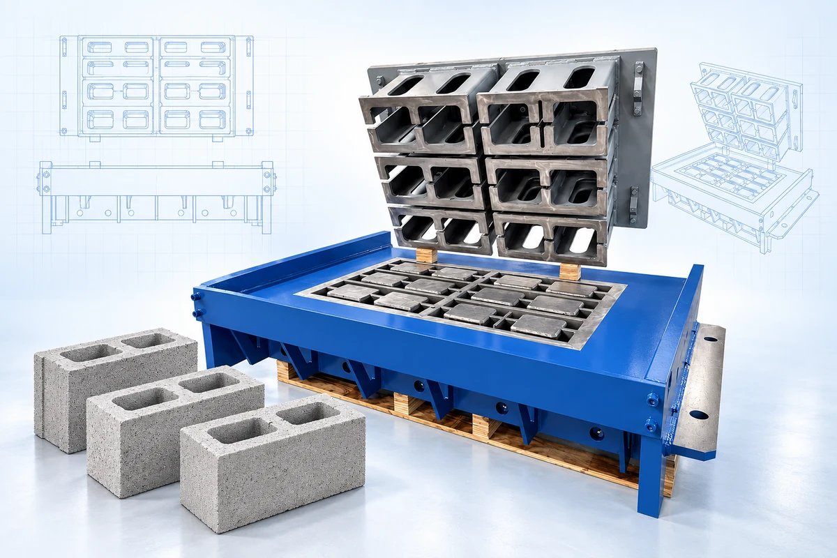
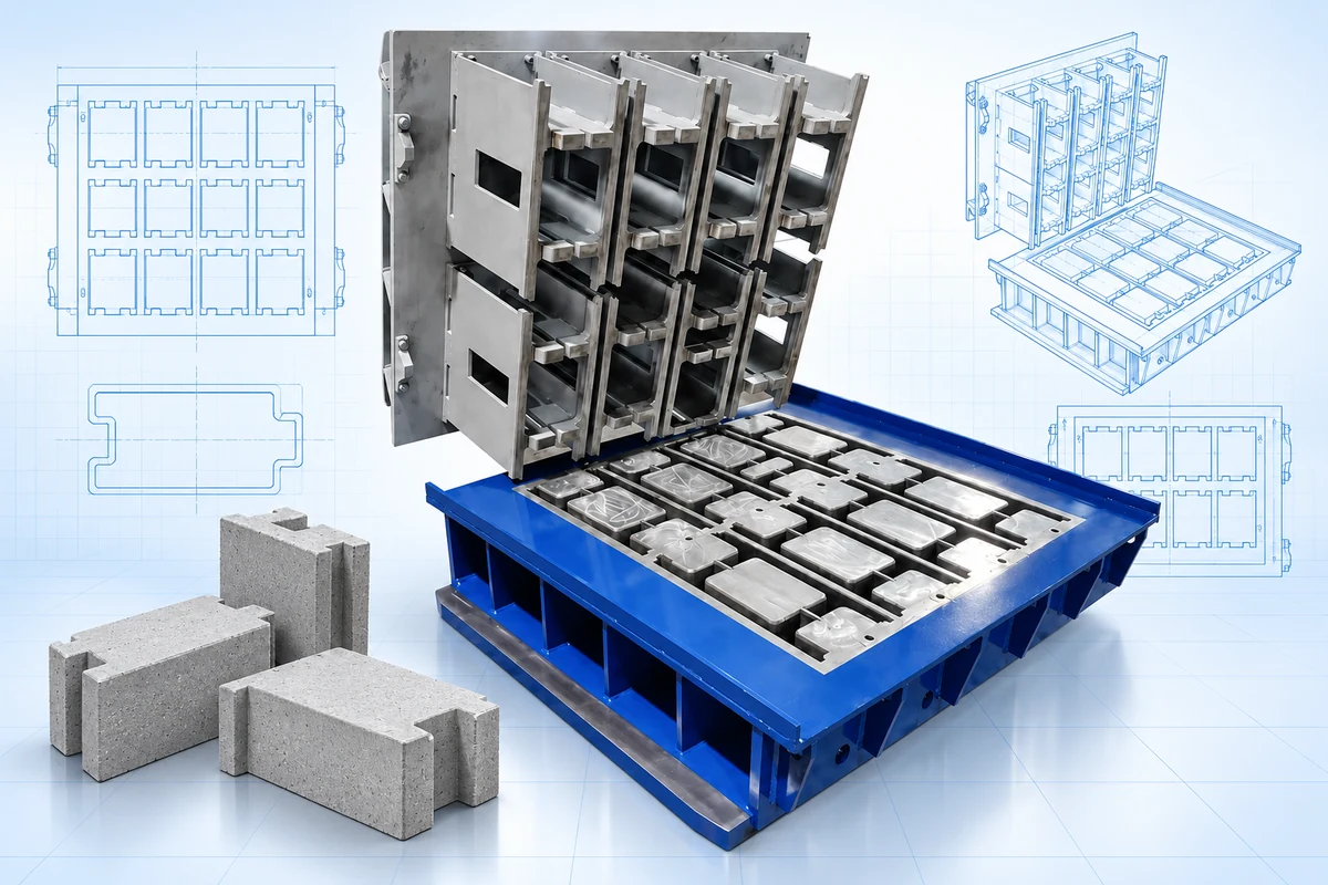
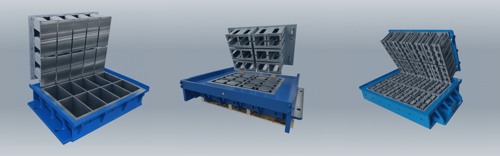
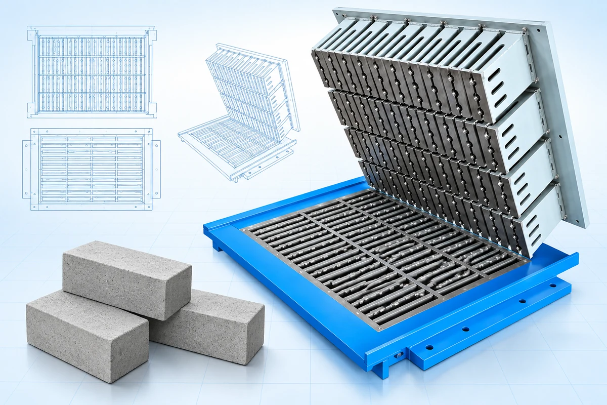
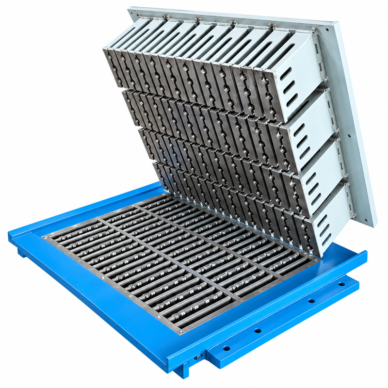
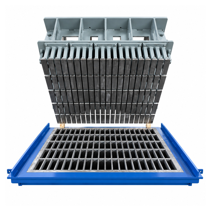
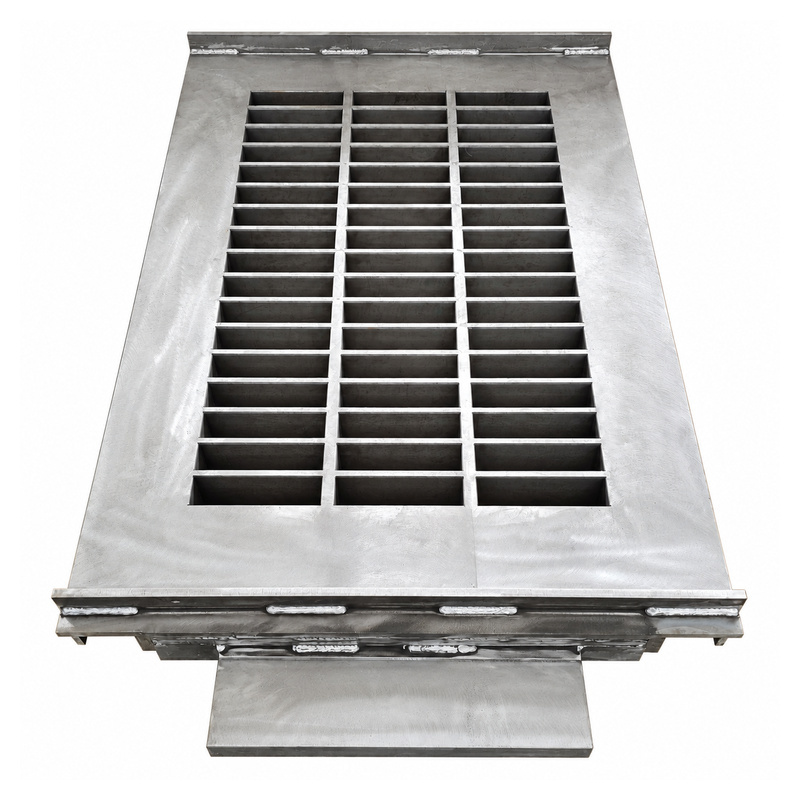
Cavity arrangements are developed around the brick dimensions and available machine working area. The layout establishes how many bricks can be formed in each cycle.
| Mould Model | BR-240 / BR-200 / Custom Solid Brick Mould |
| Block Size | Typical: 240 × 115 × 53 mm; 200 × 100 × 60 mm; 200 × 100 × 50 mm (Custom sizes available) |
| Block Height | 40–100 mm (design-dependent reference) |
| Material / HRC | Wear-resistant alloy steel; heat-treated, HRC58–62 (reference) |
| Cavities/Cycle | Custom to brick size, mould layout and machine specifications |
| Machine Brand | HAWEN / HESS / MASA / ZENITH / QUADRA / other brands (subject to fit review) |
| Machine Model | QT4-15 / QT6-15 / QT8-15 / QT10-15 / QT12-15 / QT15 / QT18 / custom models (reference; fit review) |
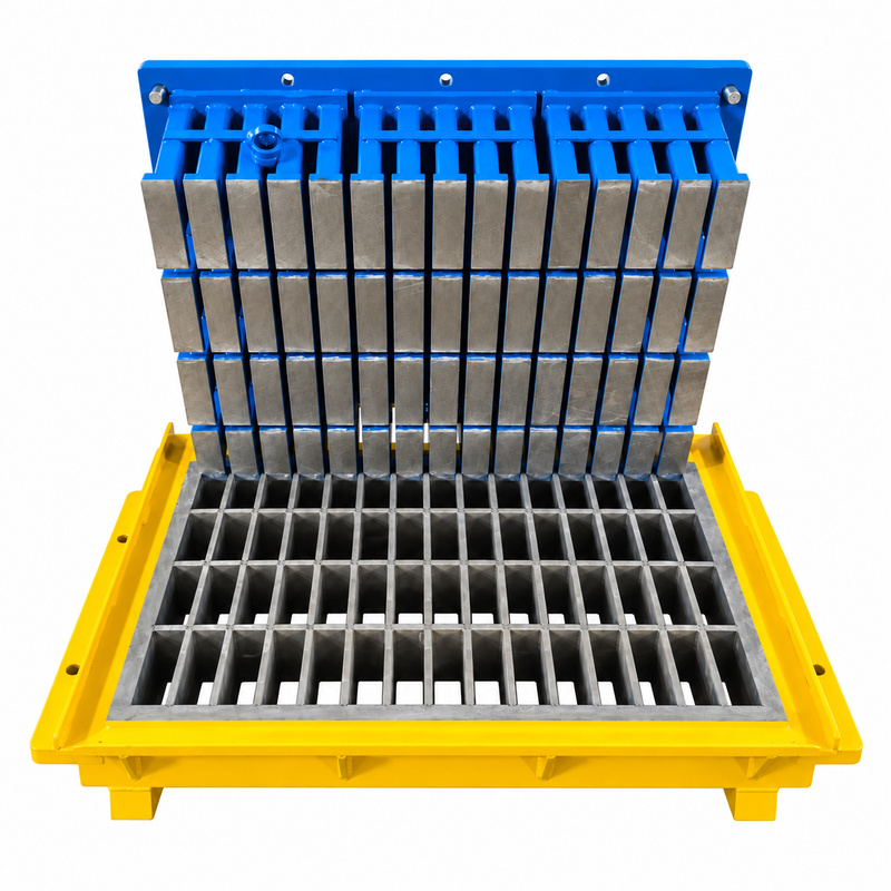
Cavity arrangements are developed around the brick dimensions and available machine working area. The layout establishes how many bricks can be formed in each cycle.
Length, width, height, chamfers, and suitable edge profiles can be incorporated into the design. This allows the mold to reproduce the brick format required by your market.
Precision machining and matching of mold and tamper components support dimensional consistency between cavities. This helps maintain a uniform product format across the production pallet.
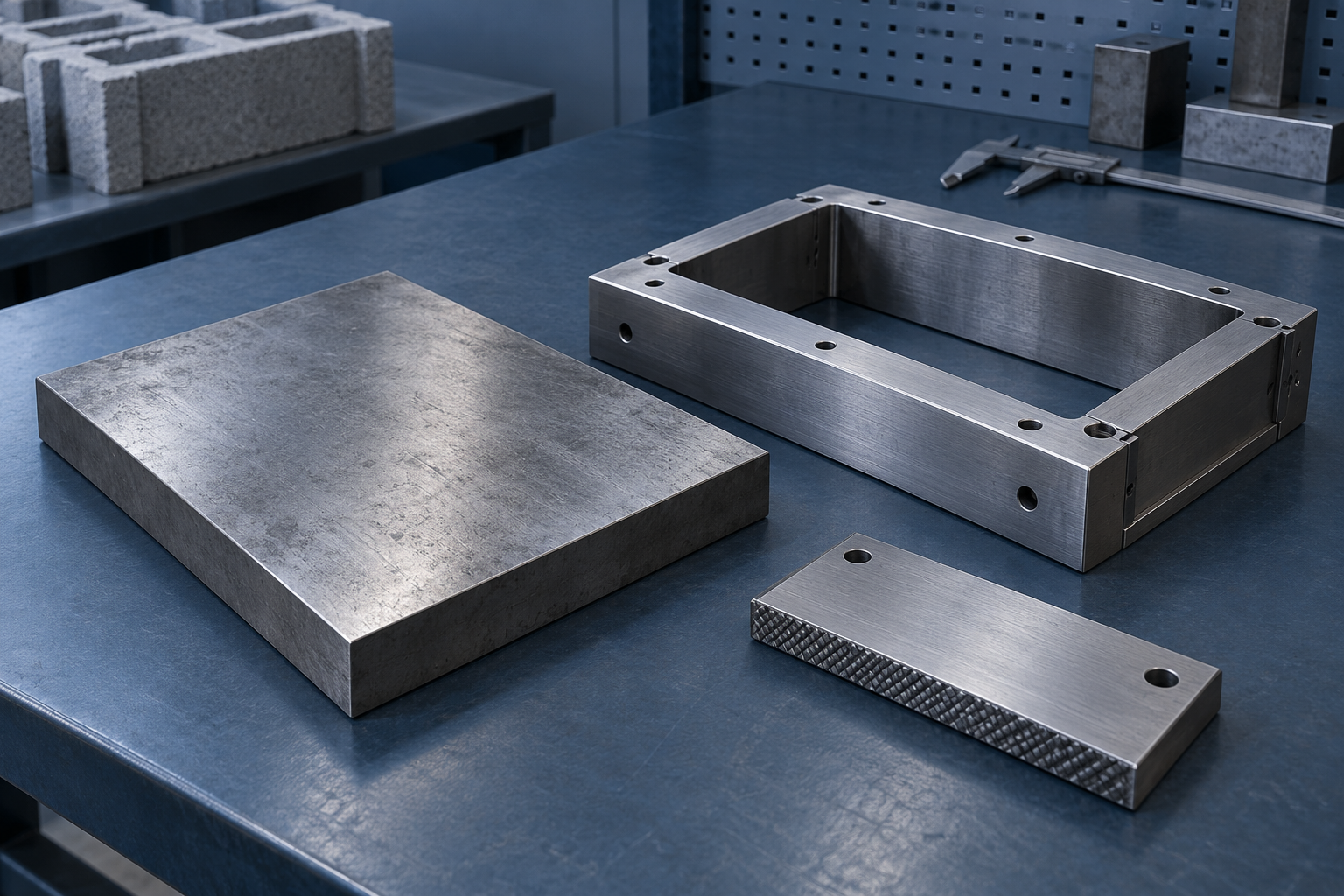
Illustrative material concept
Review block mould steel selection through component loads, abrasion, machinability and material records before agreeing the specification.
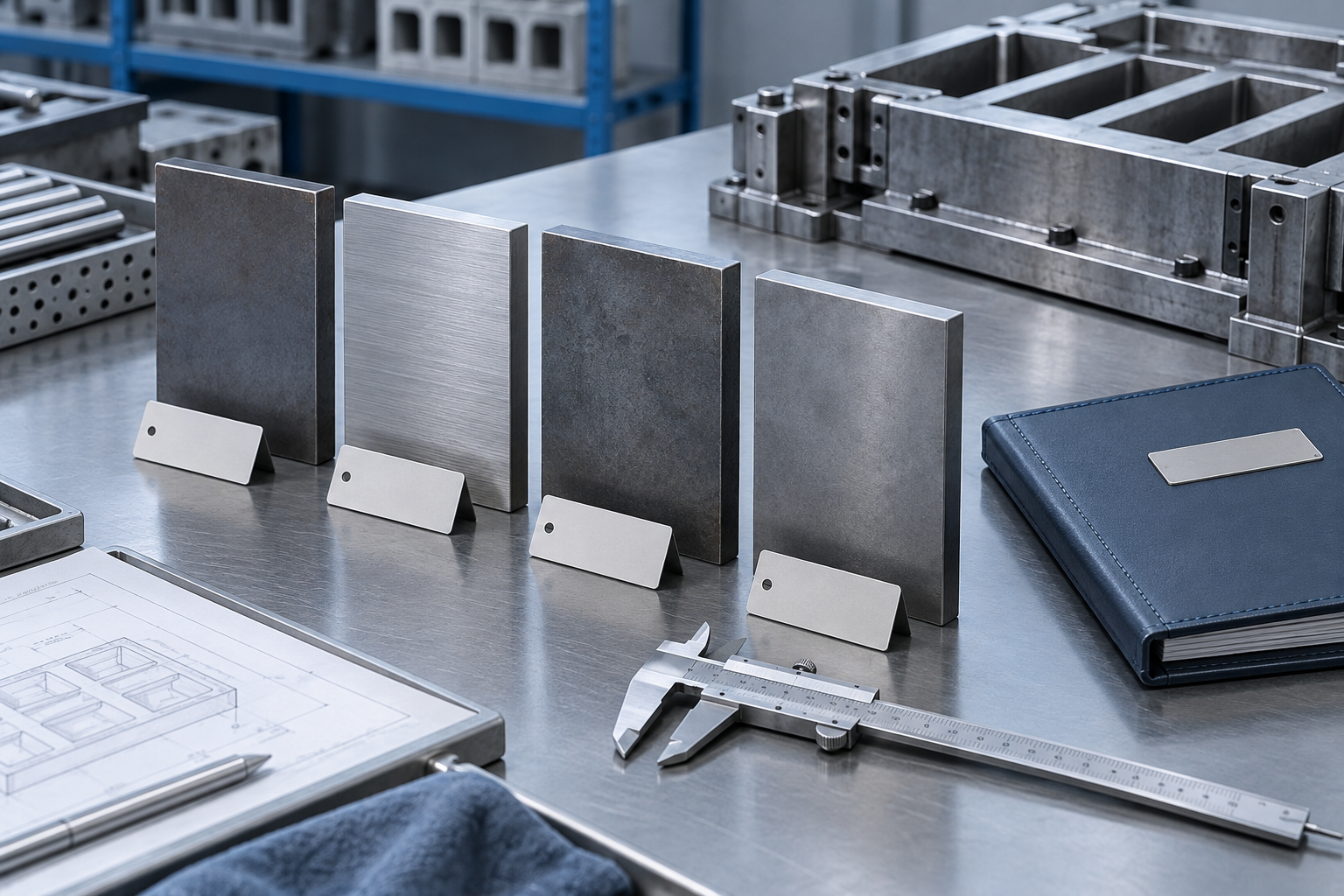
Read material guideIllustrative material concept
Check block mould material traceability by linking agreed certificates, steel batch identification, component records and inspection evidence.
Read material guidePrepare your product and machine information. Let’s review the tooling.
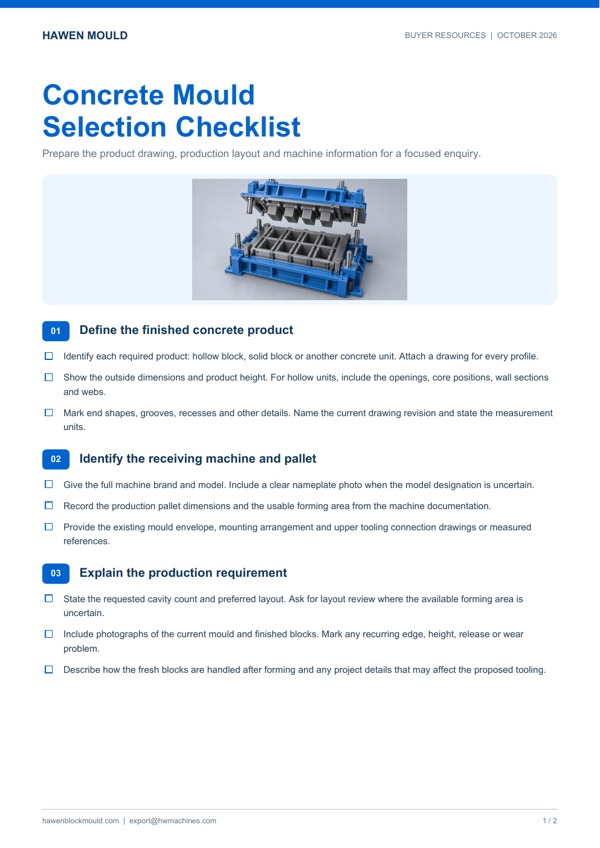
Send the finished block drawing and dimensions, machine brand and model, pallet dimensions and the mould mounting details. For a replacement, include photos or drawings of the existing mould.
The review connects the block design with the receiving machine, pallet, mounting arrangement and available forming space. Share the relevant machine and mould drawings so the interfaces can be checked before a proposal is confirmed.
Select your project purpose and describe the current tooling or the block shape you want to produce. Existing mould photos and a dimensioned product drawing help the team identify the information still needed.
Confirm the approved block drawing, cavity arrangement, machine interfaces and agreed mould specification. Include any project changes in the enquiry so the proposal can be reviewed against the latest requirements.

 Tel: +8618359454595
 Email: sale@hwmachines.com
 MP/WhatsApp: +8618359454595
 Manufacturer Address:Nanan, Quanzhou City, Fujian Province, China